aISA
Adaptive operating systems create major usability advantages when used in a tractor. They always offer the user the right operating elements with the right operating characteristics. Such operating systems are particularly advantageous in tractors, as the operating scenarios change frequently when working with the tractor. In the previous aISA research project, such an adaptive operating system was developed and a prototype validated in field tests.
Results of the aISA project
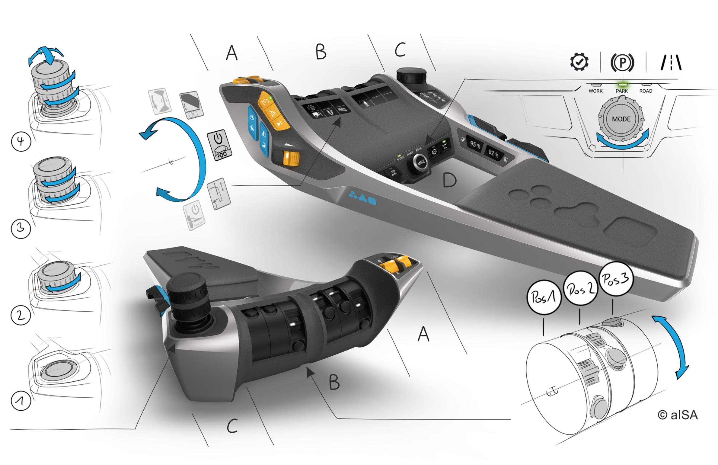
In the three-year joint project aISA (adaptive interface systems in agricultural tractors), the Institute of Construction Technology and Technical Design (IKTD) at the University of Stuttgart, the Institute of Agricultural Engineering at the University of Hohenheim (ATH) and elobau GmbH & Co. KG developed, built and tested a functional prototype of a control armrest. The testing was carried out by installing it in a Same Deutz-Fahr tractor and various field tests with different implements and drivers. The result of the methodical development was already on display at Agritechnika in 2019. The developed operating armrest is able to adaptively adjust to different operating scenarios and provide a suitable interface system that relieves the user and offers intuitive operation with a high usability and user experience. The operating elements on the armrest can be divided into several areas. Area A contains tractor-specific functions. Area B and C have been positioned according to importance for functions to operate the connected implement and include adaptive controls. Area D includes a mode switch that activates or deactivates function bundles based on the mode of operation - Work, Park, Road. Area C includes an adaptive control in the form of a joystick that can assume four different positions. The joystick is not available in position 1, as shown in Figure 1 on the left. Position 2 provides one and position 3 provides two rotational control units. In position 4, two additional axial joystick axes can be operated. Each position adjusts itself depending on the coupled implement and presents only the functions required for the situation. In addition, there is a graphic support for the user. The graphic symbols adapt adaptively when the implement is changed in order to visualize clear function assignments to the implement and the respective active part. Direct assignment to the operating element is also ensured by the spatial arrangement of the pictograms.
The adaptive control elements implemented in area B are electronically controlled rollers which obtain the optimum positioning through the characteristics of the required functions of the respective implement. Three different positions exist, which can be seen in the lower right corner of Figure 1. Position 1 provides a thumbwheel, which in vertical arrangement represents an "up/down" movement of the control element, and an optimally accessible button for confirming "on/off" functions. Position 2 provides the same controls, but the thumbwheel is horizontal to represent a "forward/backward" movement. In position 3, only the button is available. This positioning adaptivity is related to the compatibilities of the active parts, which has been implemented here in the form of movement compatibility, whereby the direction of movement of the control part matches the direction of movement of the active part.
Graphical representation of the layer method
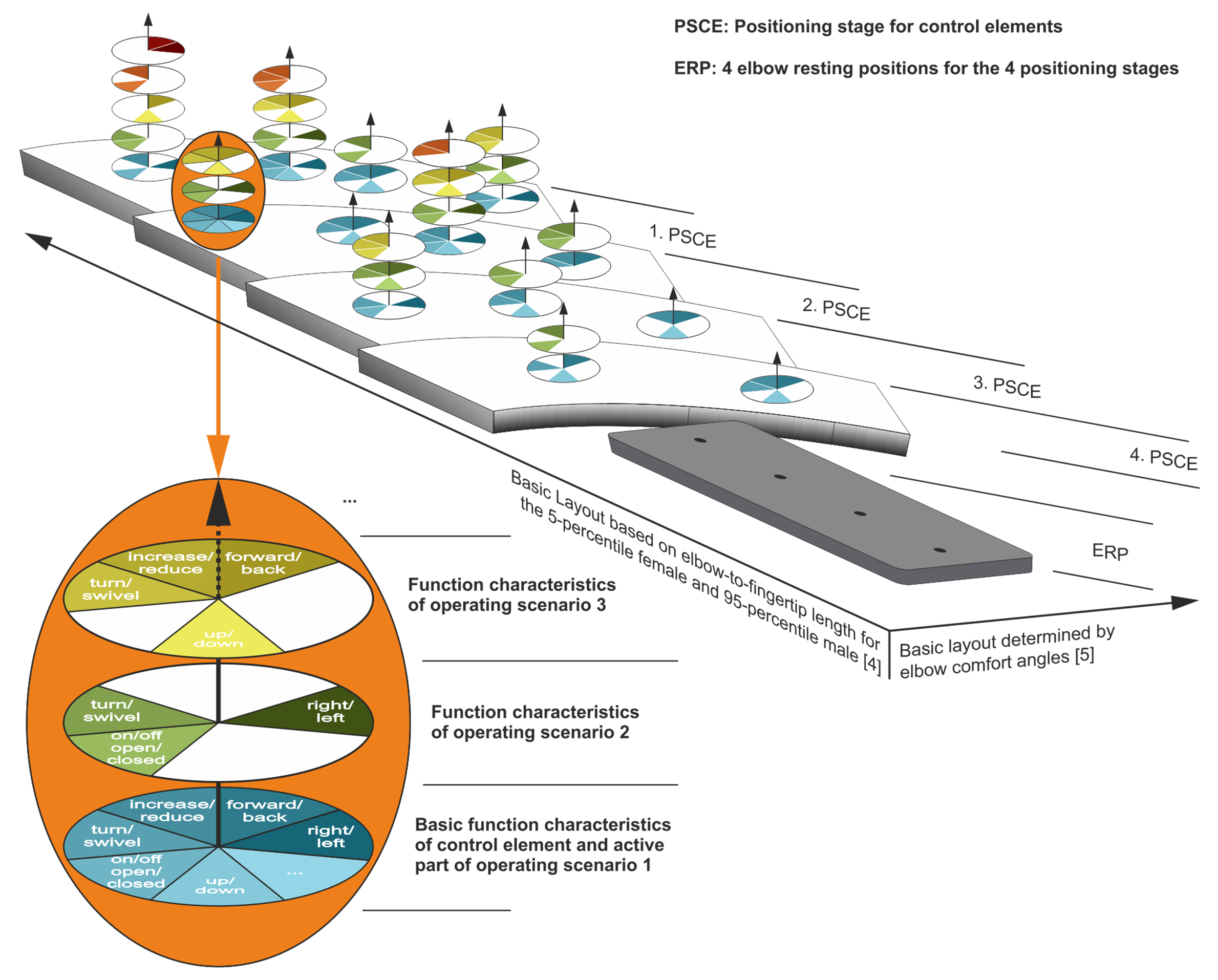
In order to obtain an optimal function positioning for the operating system and to be able to define a function shape for the adaptive operating elements, the so-called layer method was developed in the previous development step. When applying the layer method, a layer was created for each examined work device in order to obtain an optimal function assignment for the respective scenario. When combining these layers, overlaps were found which had to be solved with adaptive control elements. These overlays are shown in Figure 2 with superimposed circles or circle segments and signal all the function characteristics that a control element should be able to perform at the specific position in order to ensure optimal operation. The development of adaptive control elements enables them to perform the various functions required. On this basis, the above-mentioned adaptive control elements could be developed and design recommendations for position and availability could be established.
During the project, the following industrial property rights "Adaptive operating device and method for adapting an operating device" with patent numbers DE 10 2018 120 732.8 and DE 10 2019 117 604.2 were applied for. The rights were transferred to the project partner elobau GmbH during the project.
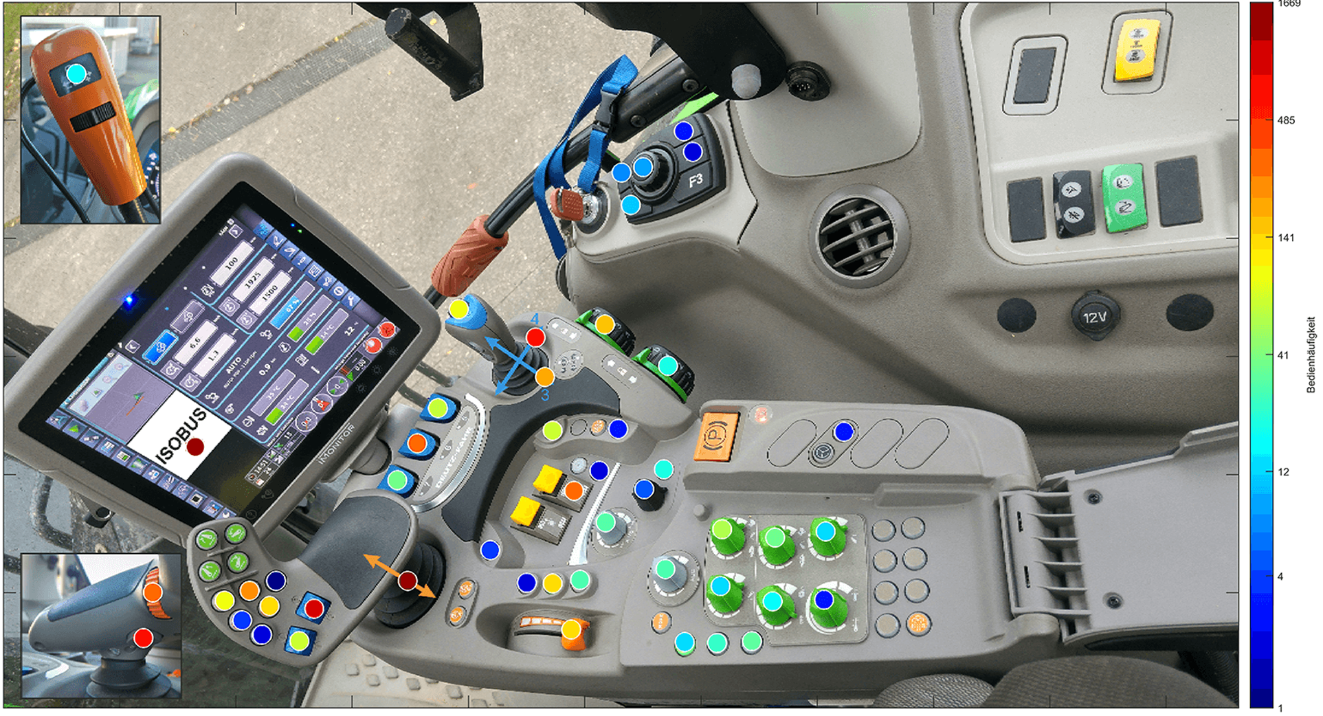
Picture 3: In the analysis phase, the operating frequencies of the actuators on a current control armrest were examined when using different attachments. The figure visualizes the frequency distribution of operation.
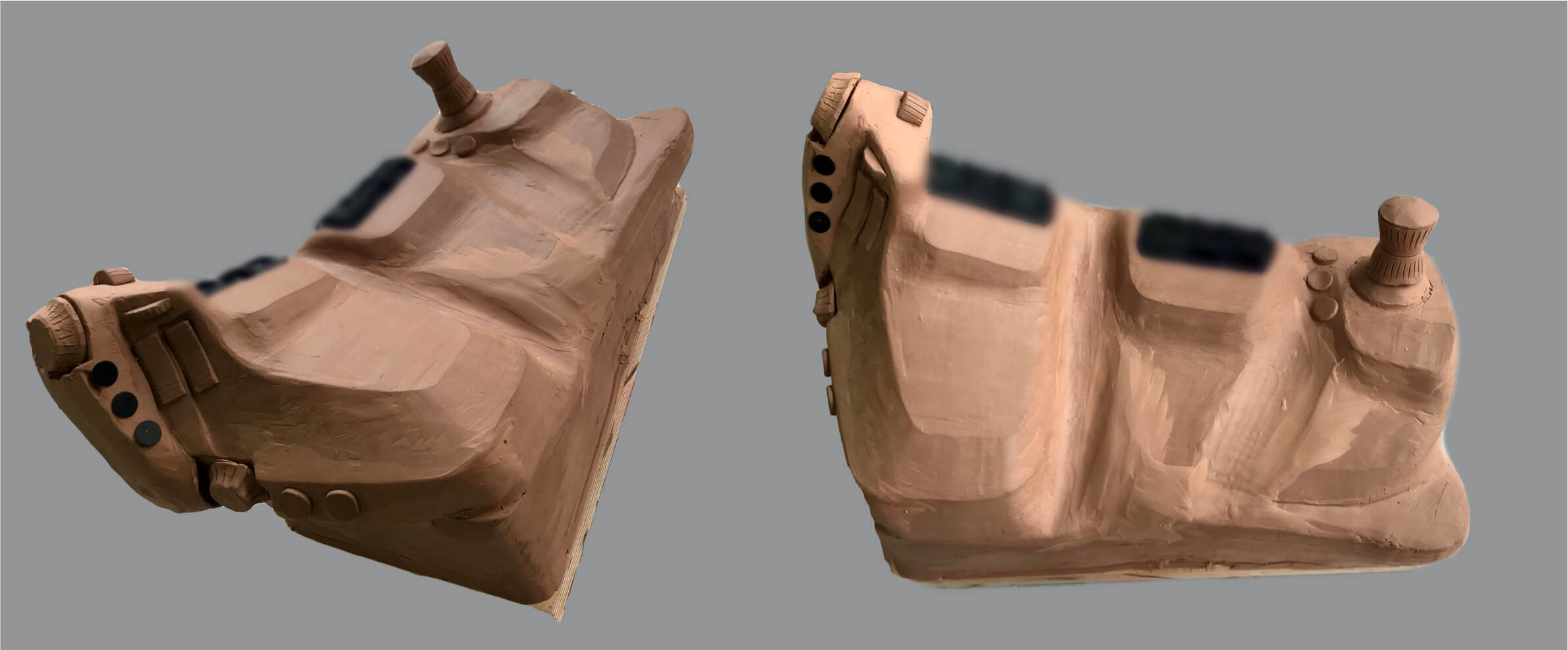
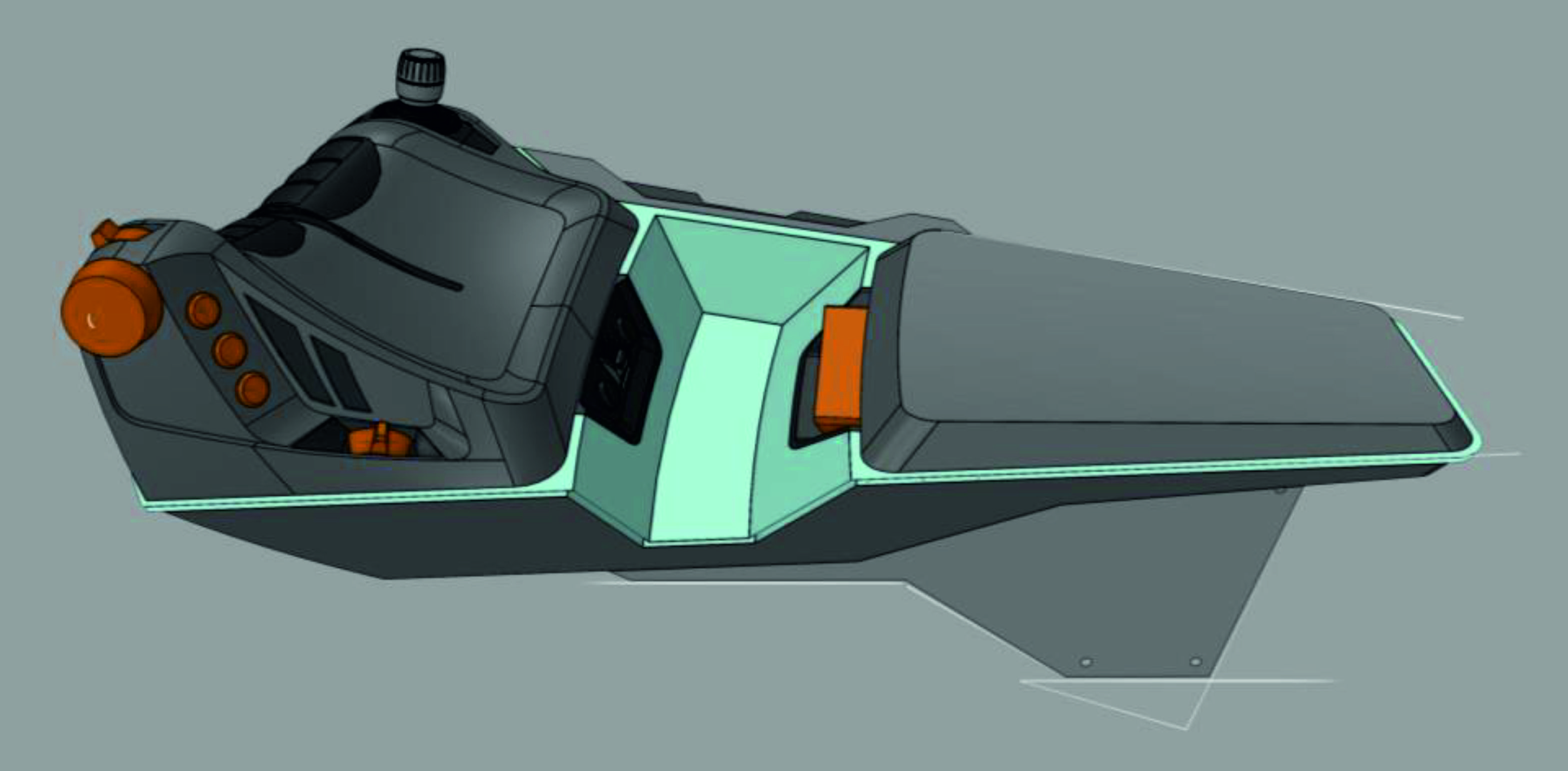
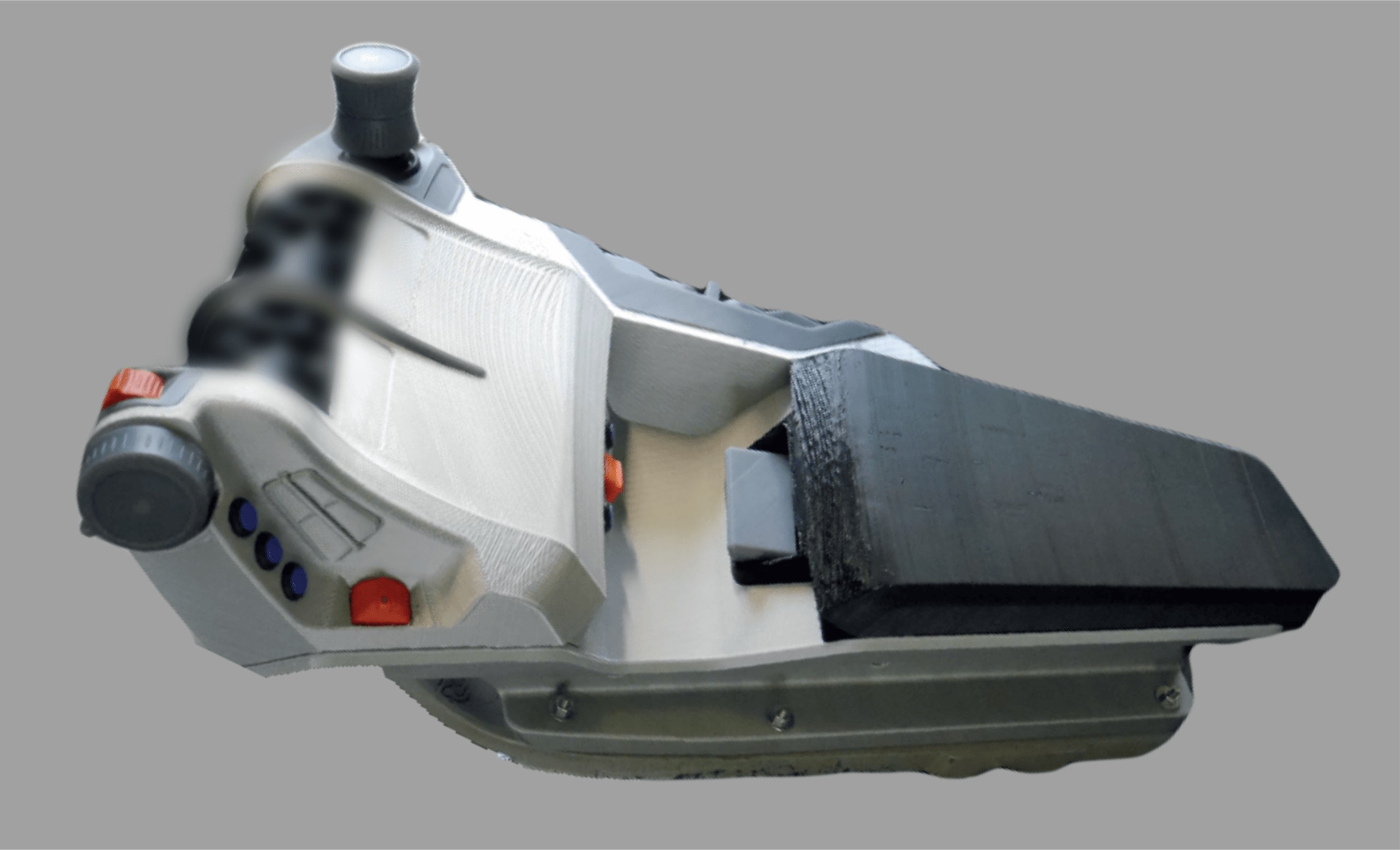
Picture 4: After the analysis phase, initial solutions were developed and implemented in the form of foam and clay models.